At first glance, electrical diagrams (hereinafter also “EDs”) might appear intimidating; however, they are indispensable tools for anyone involved in working with electrical systems (hereinafter also “ES”).
Whether you’re a certified electrician, a budding DIY enthusiast, or someone aiming to grasp the basics, this guide will walk you through the process of reading and interpreting EDs.
Unraveling the Four Basic Types of Electrical Diagrams
EDs are vital for visualizing and comprehending electrical systems. There are four primary categories of these diagrams, each serving a distinct purpose:
1. Schematic Diagrams
These are the most common EDs, providing a simplified and abstract representation of an electrical circuit. They utilize standard symbols to depict components and their relationships, focusing on the functional aspects of the circuit without delving into the physical layout or component placement.
2. Wiring Diagrams
These offer a detailed view of electrical circuits, showcasing the physical placement of wires and components. Wiring diagrams are invaluable for understanding the connections and wire pathways within a system, frequently employed in the design, installation, and maintenance of electrical systems.
3. Line Diagrams
Also known as single-line or one-line diagrams, these simplify the system’s appearance by representing it with one or a series of lines. Common in the industrial sector, line diagrams depict power distribution and control systems, highlighting essential components and connections while omitting complex details for clarity.
4. Block Diagrams
These provide a high-level overview of a system or subsystem, representing it as interconnected blocks or modules. Each block symbolizes a function, component, or subsystem, facilitating the display of relationships and interactions between different system parts.
Engineers, electricians, and technical specialists rely on these diverse diagrams to comprehend, design, install, maintain, and troubleshoot electrical systems and circuits, tailoring their choice depending on the specific requirements of the task at hand.
Mastering the Language of Symbols
Becoming adept at interpreting various icons is a primary challenge when learning to read electrical diagrams (EDs). We will guide you through a selection of universal icons found in EDs, ranging from elementary components like bulbs and switches to more intricate elements such as transformers and capacitors.
The language of circuit diagrams encompasses a series of universally recognized pictorial icons, known as electrical icons or indicators. They are systematically utilized to portray electrical and electronic elements and their interconnections in diagrammatic representations. The incorporation of these icons is essential for communicating detailed information about complex electrical pathways and configurations.
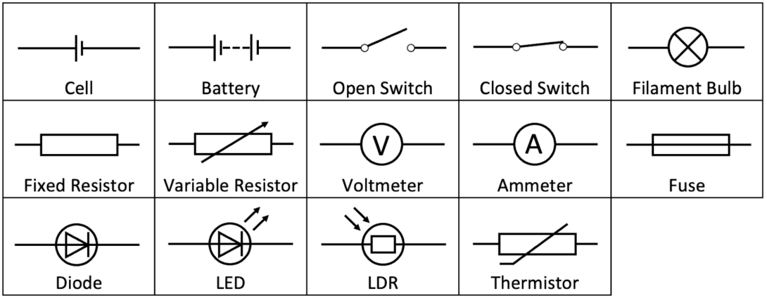
Here are some common electrical symbols:
| Symbol | Description |
|---|---|
| Resistor | Represents a passive component that restricts the flow of electrical current. It’s usually depicted as a zigzag line. |
| Capacitor | Symbolizes a component that stores electrical energy. The symbol consists of two parallel lines. |
| Inductor | Represents a coil of wire that resists changes in current. The symbol often looks like a coil or a series of loops. |
| Diode | Depicts a semiconductor device that allows current to flow in one direction only. The symbol resembles an arrow pointing in the direction of current flow. |
| Transistor | Represents a semiconductor device used for amplification, switching, and signal processing. There are various symbols for different types of transistors, including NPN and PNP. |
| LED (Light Emitting Diode) | Signifies a specialized diode that emits light when current flows through it. The symbol is a diode with two arrows, one pointing outwards to indicate light emission. |
| Switch | Depicts a device that can open or close a circuit to control the flow of electricity. The symbol typically looks like a line with a gap or break in it. |
| Fuse | Represents a safety device that melts or breaks when excessive current flows through it. The symbol is often a line with a “wavy” section in the middle. |
| Ground (Earth) | Signifies a connection to the ground or Earth. The symbol is a simple horizontal line with three downward-pointing lines. |
| Battery | Symbolizes a source of electrical energy. The symbol consists of one or more cells with positive and negative terminals. |
| Transformer | Represents a device used to change the voltage levels of an alternating current (AC). The symbol usually resembles two coils connected by a line. |
| Motor | Depicts an electric motor. The symbol varies depending on the specific motor type. |
| Generator | Symbolizes an electrical generator or alternator. The symbol is often a circle with lines or arrows to represent the rotation and generation of electricity. |
| Amplifier | Represents a component that increases the strength or amplitude of a signal. The symbol is typically a triangle with an input and an output arrow. |
| Relay | Signifies an electromagnetic switch or control device. The symbol resembles a coil and one or more switch contacts. |
| Grounding (Chassis Ground) | Indicates a connection to the metal chassis or enclosure of a device. The symbol typically looks like a horizontal line with three lines radiating downward, similar to the ground symbol but without the horizontal line. |
The above are merely illustrative examples amid a vast array of electrical icons that populate schematic representations. Acquiring a thorough comprehension of these icons is pivotal for both crafting and interpreting EDs, thereby equipping professionals and enthusiasts with the capacity to efficiently design, diagnose, and uphold electrical pathways.
Demystifying Wiring Diagrams
Electrical diagrams are compositions of lines, icons, and annotations that collaboratively elucidate the interconnections and affiliations amongst diverse components. We aim to illuminate the core tenets that govern these diagrams and facilitate a profound comprehension of the rationale underpinning their structure.
Such diagrams serve as methodical illustrations, shedding light on intricate electrical configurations. They empower both specialists and aficionados to proficiently traverse, construe, and oversee electrical assemblies. Each component, connection, and inscription is intentionally crafted to impart distinct data, integral for safeguarding and enhancing the functionality and safety of electrical configurations.
Unraveling the Complexities of Electrical Diagrams
The prospect of delving into electrical diagrams can be intimidating at first glance. Nevertheless, adopting an informed methodology renders the exploration markedly approachable. In the ensuing discourse, a meticulous, sequential tutorial is unveiled to disentangle the intricate facets of EDs.
Key Steps to Unravel Electrical Diagrams:
- Foundation Knowledge: Initiation into the realm of EDs commences with an immersive exploration of lines, icons, and explanatory notes that collectively comprise the diagram;
- Navigating the Key: Frequently, EDs are accompanied by a comprehensive key or legend that deciphers the employed icons. A preliminary exploration of this element is advised;
- Power Source Identification: Ascertain the locus of the energy source, typically denoted by battery or voltage source symbols;
- Line Tracing: A meticulous examination of the connections and conduits, portrayed by lines, unveils the electrical trajectory, crucial for understanding energy flow;
- Component Recognition: Icons symbolizing circuit elements like resistors and diodes are decoded with assistance from the accompanying legend;
- Connection Interpretation: Discern the methodology of component interlinking. Diverging trajectories and intersection patterns offer insights into connection presence or absence;
- Annotation Decoding: Evaluate supplementary data inscribed on the diagram, facilitating nuanced comprehension of component specifications;
- Circuit Traversal: Commence at the energy source and meticulously follow the intricate pathway, taking note of component transitions and energy flow dynamics;
- Grounding Icon Identification: Typical grounding symbols, resembling downward-pointing arrows, designate the circuit’s foundational reference, ordinarily at null potential;
- Control Element Analysis: Should the diagram incorporate regulatory components like switches, an in-depth comprehension of their operational impact is essential;
- Endurance and Application: Mastery in ED interpretation is progressive, honing through persistent practice and graduated exposure to complexity;
- Resource Consultation: Unfamiliar icons and elements warrant reference to instructional materials, online databases, or the diagram’s legend;
- Implementation and Verification: In practical applications, adhere stringently to the diagrammatic guidelines, validating each implementation phase against the schematic blueprint.
Patience and consistent practice are the cornerstones of proficiency in ED interpretation. As expertise is cultivated, the ability to adeptly interpret intricate diagrams and apply them in diagnostic, restorative, or design capacities is enhanced.
Conclusion
Mastering the art of reading EDs is a significant milestone in acquiring the skills to work with electrical systems. Whether an electrician, an engineering student, or a DIY enthusiast, these insights are invaluable. With this comprehensive guide, you’ll unveil the mysteries of EDs and confidently undertake electrical engineering projects, equipped with the knowledge to interpret and apply these intricate illustrations effectively.
The journey to proficiency in handling electrical systems is intertwined with the mastery of deciphering these diagrams, a skill that unfolds progressively with dedication and practice.